PCS® Insights
Sharing Industry Knowledge, Lessons-Learned and Published Presentations
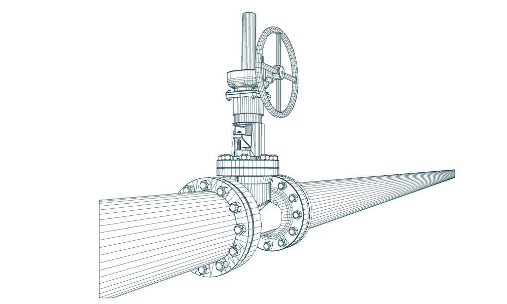
Preventing Fracture in CO2 Transmission Pipeline Systems
Fracture | preventing the pipeline from cracking
One of the consequences of the transportation of CO2 as a supercritical liquid is that it behaves as a high-vapor pressure liquid. This behavior has significant implications for the fracture control design of a CO2 pipeline. The requirements for the fracture control of the line pipe have been considered during the course of design of the pipeline system.
- the pipe must exhibit ductile as opposed to brittle behavior in the operating temperature range.
- pipe materials must have adequate toughness to tolerate large flaws caused by sharp cracks or mechanical damage. The requirement is that if a fracture did occur, in spite of the large flaw tolerance, the pipe must have adequate fracture toughness to arrest the fracture (fracture propagation control).
Fracture control is an important consideration in the design of a transmission pipeline. There are two aspects to a fracture-control plan for a pipeline:
- Fracture initiation and control
- Fracture propagation and control
Fracture initiation control is achieved by designing the pipeline to reduce the likelihood of failure of defects, whether introduced during manufacturing, transportation, construction or operation. It encompasses many aspects of design including wall thickness, product composition, operating conditions, and material selection. For the Project pipelines, fracture-initiation control was achieved by:
- Increasing the wall thickness at critical installation areas such as road bores, horizontal directional drill crossings, and mainline valve stations
- Installing product analysis tools (gas chromatographs, water analyzers) to insure the product meets the design specification
- Minimizing the amount of aboveground pipe to limit thermal expansion and pressure transients in the pipeline
- Additional depth of cover to prevent third-party damage (4 ft to top of pipe instead of 3 ft)
- Using electric actuators on mainline valves to prevent “slam shut” conditions producing pressure transients, i.e. water hammer effect
- Full inspection staff at pipe mill to insure rejected pipe or pipe outside of specification is not inserted into the pipeline
Fracture propagation control is achieved by ensuring that the toughness of the line pipe steel is sufficiently high to arrest propagating fractures. Alternatively, crack arrestors could have been installed. Crack arrestors are typically short, heavy wall pipe segments welded into the pipeline. For long, transmission pipelines crack arrestors can pose both cost and logistic issues. For projects where the pipe is manufactured to order, it is more efficient to specify enhanced metallurgy and mechanical properties than to design, source and install crack arrestors. However, there are some conditions where the required toughness calculated to arrest a propagating crack can be beyond the capabilities of the steel producer. In such cases, crack arrestors may still be required.
In order to comply with Title 49, Code of Federal Regulations, Part 195, §195.111, mitigation of propagating fractures was achieved by controlling the minimum toughness of the produced pipe steel. The Battelle Two-Curve Method (TCM) was utilized to determine the minimum toughness for the pipe specification. As an example, one of our pipeline inlet conditions for the designed, maximum flowrate was defined as 2,140 psig and 110°F. Using the Peng-Robinson EoS and assuming an isentropic expansion, the decompression pressure was determined to be:
Design Composition Decompression Pressure: 990.2 psig @ H = -87.2 BTU/lb
Worst Case Decompression Pressure: 1023 psig @ H = -86.08 BTU/lb
The following Charpy toughness values were determined and specified for the pipe order:
Table 1: Summary of Specified Minimum Toughness Value
|
Outside Diameter (in) |
Wall Thickness (in) |
Grade (API 5L) |
Minimum Toughness (ft-lb) |
|
16 |
0.457 |
X70 |
32 |
|
16 |
0.548 |
X70 |
21 |
Since the calculated toughness values are well within the typical values found in X70 grade line pipe, there was no need to install additional crack arrestor material to mitigate any ductile fracture propagation.
The pipe has been designed against fracture propagation in accordance with the API Specification 5L, and ASME B31.4 standard and the fracture toughness tests have been performed complying with Annex G of API specification 5L. Also, the Charpy impact test data for the 0.457” and 0.548” W.T. cases are at 100 percent shear area with the minimum requirement being 85 percent to insure ductile behavior.
Initially, the design was based on the nominal CO2 purity stream. However, the initial conditions were modified to a worst case of 2140 psig and 110° F, representing the pipeline inlet and/or pump discharge location. Since most mechanical testing at the pipe manufacturer is normally performed at the lowest anticipated service temperature (LAST) for compliance with API 5L, additional mechanical testing was specified at higher temperatures (HAST – Highest Anticipated Service Temperature) to represent the operating range of the pipeline.
It was clear from the fracture analysis performed that while the design literature available and surveyed considered dense phase CO2 pipeline transportation to be fairly mature, the transition to anthropogenic sources and increased levels of impurities have highlighted a significant knowledge gap. This knowledge gap is evident in the uncertainties surrounding the equation of state (EoS) for determination of the decompression pressure, particularly pronounced for compositions containing less than 95% CO2. The additional measures of testing at higher temperatures as well as defining a minimum value of a single Charpy test specimen in lieu of the typical “all heat average” definition were done to mitigate these unknowns and produce a more conservative design.
This post is a continuation of a November Insight which focused on hydraulics in the design of an anthropogenic CO2 Pipeline. Click here to read the previous post.
Article Details
Author: Mike Istre, P.E.
Chief Engineer
PCS® Lafayette
More Information
Contact Us
We would appreciate any opportunity to assist you, and to connect you with the right person at PCS ® to address your needs and answer any questions.
Request Info Call Us 1-800-643-8306